
TIME ROLLING · OIL & GAS PRODUCTION
Electric Submersible Pump Systems
Time Rolling electric submersible pump (ESP) systems combine downhole pumping equipment with surface power and control. Match the pump stages, motor, protection and electrical components to the well’s lift, flow rate and operating conditions.
- Published pump lift
- Up to 3,000 m
- Pump flow range at 50 Hz
- 22–5,640 m³/day
- Integrated system components
- Downhole to surface
Submersible centrifugal pumps
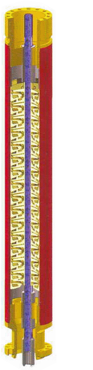
A multistage centrifugal pump converts motor power into pressure and velocity to lift well fluid to the surface. Nickel-alloyed iron stages combine rotating impellers with stationary diffusers.
Floating-stage designs absorb thrust within the pump stages. Compression-stage designs transfer downward thrust to the protector thrust bearing, supporting a broad range of flow rates.
Radial-flow stages are typically more efficient below 380 m³/day. Mixed-flow stages suit higher rates and offer improved gas handling. Stage count determines the required head; stage size determines capacity.
- Stainless steel housings or Monel-coated carbon steel housings for corrosive conditions.
- Tungsten carbide bearings for radial stability in abrasive, sandy service.
- Higher-strength shafts where stage count and shaft loading require them.
- Single-stage arrangements and upper, middle and lower sections with spline couplings for system configuration.
- Pump series
- 86 · 101 (98) · 130 · 172
- Power frequency
- 50 Hz
- Lift
- Up to 3,000 m
- Flow rate at 50 Hz
- 22–5,640 m³/day
- Published flow range at 60 Hz
- 166–42,569 BPD
Oil and gas separators
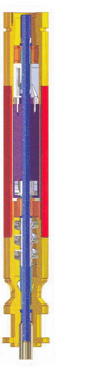
Installed between the protector and pump, a rotary gas separator helps address free gas that can cause gas locking, reduced lubrication and lower pump efficiency. Centrifugal force separates gas from the fluid; gas vents to the annulus while liquid enters the pump.
Single-stage and tandem separators are available. The tandem configuration adds a second separation stage; the published comparison reports a 5–10% improvement in separation effect. Wells with low gas content may use a pump intake without a separator.
- Series
- 86 · 101 (98) · 130
- Connection
- Spline coupling
- Configurations
- Single-stage or tandem
Motor protectors

The protector sits between the submersible motor and the separator or intake. It balances pressure, isolates motor oil from well fluid, provides an oil reserve and carries axial load from the centrifugal pump.
Mechanical seals, settlement or bag chambers, a thrust bearing and radial bearings form the protection assembly. Dielectric motor oil fills the bearing cavity, with a connecting system maintaining pressure balance.
Labyrinth and labyrinth-bag chamber configurations are selected for well conditions, motor temperature class, power and pump lift. Special designs can provide increased sand resistance, corrosion resistance or bearing capacity.
- Series
- 86 · 101 (98) · 130 · 143 · 172
- Sections
- Single, or upper and lower stages
- Connection
- Spline coupling
Submersible motors

Two-pole, three-phase squirrel-cage induction motors drive the ESP system. Power arrives through the submersible cable, and refined mineral oil provides dielectric strength and bearing lubrication. Well fluid flowing past the housing dissipates motor heat.
Motor power, voltage, insulation and efficiency configuration are selected for downhole conditions. Single motors or upper, middle and lower motor sections can be combined through spline couplings. Synchronous submersible motors are also available on request.
- Speed
- 2,900 rpm at 50 Hz · 3,500 rpm at 60 Hz
- Temperature classes
- 90 °C · 120 °C · 150 °C · 180 °C
- Series
- 95 · 114P · 114J · 114PH · 114Y · 138 · 143 · 188
- Working voltage
- 200–3,500 V
- Working current
- 10–120 A
Downhole temperature and pressure sensors
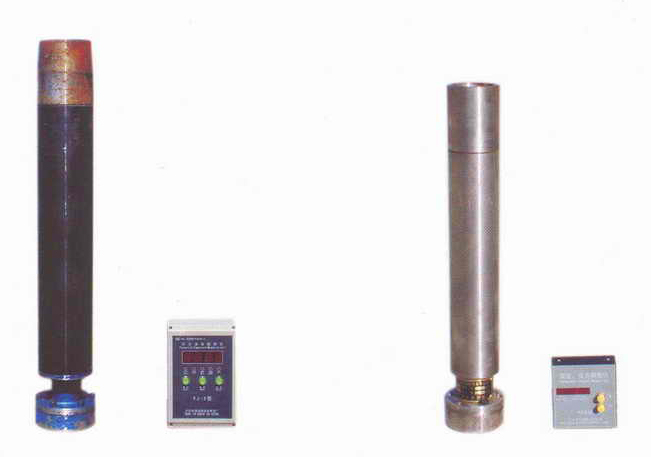
Installed at the tail of the ESP assembly, the sensor system measures temperature and pressure at pump depth. Downhole primary instruments and secondary instruments provide numerical display and storage of measured values.
- Available models
- YJ-1 · YJ-2
Submersible power cables
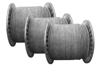
Flat and round ESP cables are available to suit mechanical loading, temperature and chemical exposure. Flat cable is an option where clearance between tubing and casing prevents the use of standard round cable.
Motor lead extensions (MLE) are also available. Cables are manufactured to applicable API requirements and selected as part of the complete ESP electrical system.
- Working voltage
- 3–6 kV
- Working temperature
- 90–204 °C
ESP switchboards
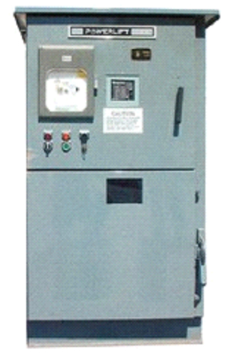
The switchboard protects the pumping system by shutting down at preset alarm thresholds and preventing restart until conditions permit. Configurations range from push-button contactors with overload protection to assemblies with fused disconnects, recording ammeters, restart timers and remote control.
Underload and overload indication can be incorporated. Standard switchboard sizes are 400 V, 1,000 V, 2,000 V and 3,000 V.
- Installation conditions exclude flammable or explosive media, corrosive gases that damage insulation, conductive dust and severe shock.
- Altitude
- Up to 2,000 m
- Ambient temperature
- −30 °C to +50 °C
- Relative humidity
- Up to 85%
- Power supply
- Three-phase · 50 Hz or 60 Hz
- Working voltage
- 400 V–4.2 kV
- Working current
- 0–200 A
ESP transformers
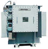
Outdoor, oil-immersed, self-cooled transformers use a three-phase, three-wire input. Output voltage can be adjusted through five-position, seven-position or other tap arrangements, with duplex or triplex winding structures.
Low-voltage winding options and special transformers for a range of frequency requirements are available to match the installation.
- Altitude
- Up to 2,000 m
- Ambient temperature
- −45 °C to +45 °C
- Input voltage
- 0.4 kV · 6 kV · 10 kV · 35 kV
- Output voltage
- 0.4–3 kV
- Rated capacity
- 10–830 kVA
ESP downhole system configuration
The downhole assembly brings the pump, intake or gas separator, protector and motor together. Review the complete configuration against well geometry, fluid conditions and power requirements.

